| Employer: | National Electric Company | | Project: | TPP Varna | | Subproject: | | | Design: | SYSTEMS FOR CONTROL of power units № 4, 5 and 6 in Varna TPP | | Main contractor: | Start Engineering JSCo. | | Subcontractors: | AMEES Ltd., KARENA - Varna | | Kinds of activities: | Design, putting into operation and tuning | | Performance: | 1998 |
|
SYSTEMS FOR CONTROL of power units № 4, 5 and 6 in Varna TPP
During the last few years, the problem for the modernization of the control of our energy capacities became actual, in order to fulfill the requirements, defined by UCPTE, which coordinates the work of the energy companies from the European countries. In connection with the provision of a good coordinate work with the energy systems of the neighbor countries, it is very important to improve the quality of the electrical energy and to assure the necessary exploitation reliability of the power units, as well as the system as a whole.
For the satisfaction of the increased requirements to the energy system and for control from ASDC (Automated System for Dispatch Control), the managements of NEK and Varna TPP took the decision for a stage implementation a microprocessor system for units № 4, 5, 6 in Varna TPP.
The foundations for the building of an Information and Control Microprocessor System in Varna TPP were made in 1998, with the putting into operation of the first, based on Teleperm XP system, consisting of an automating processor (base station for control), one operator station and an engineering station.
The design, the putting into operation and the tuning were executed by a team of specialists from Start Engineering, AMEES - Radnevo, KARENA - Varna and Varna TPP.
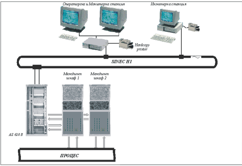
The configuration of the implemented on Unit №6 TELEPERM-XP system is shown on fig. 1. It consists of a processor station AS620B, operator station with a possibility for two monitors, engineer station and a connecting trunk line.
Figure 1. System architecture of Unit №6 before the extension
The main goal of the system was the implementation of a dispatch control for power unit №6. This included a control of the produced electrical power and the fuel-air regime of the boiler. Except these most important systems for automatic control, in this first realization of the system were also included: regulators for temperatures of primary and secondary steam, drum level, primary air pressure and thinning out in the furnace chamber. In order to assure the work of Unit №6 at a changing and respectively thermal load were realized the following functional-group controls: changing of the speeds of the air fans; turning on of high pressure heaters.
A coordinated control of the scheme "leading turbine" was accomplished. The regulator of power gets a setpoint from ASDC or locally from the operator and influences the regulating valves of the turbine by the mechanism for control (МУТ). The setpoint for power is treated in a unit for restriction, defining the real regulation range for alteration of the unit, as well as in a limiter for the speed of change of the setpoint, which determines the change of the setpoint in the limits of the admissible speed for changing the load. Main limitation factors for the maximal load were taken into consideration, like the switching off the High Pressure Heater, temperature drop of the overheated steam, increase of the pressure in the regulation stage of the turbine, heating of the rear end of the turbine. The results from the work of the unit for limitation are led to the power regulator, as well as to the dispatch service. During the work with a local setpoint, an influence on the system's frequency was foreseen, for the coordination of the primary and secondary regulation. At a setpoint from ASDC it was accepted that this coordination is made on a higher level.
The setpoint for power to the regulator is led also simultaneously to the heat load and common air regulators. The regulator for heat load was realized by the scheme setpoint - flow of fuel (evaluated indirectly out of the sum of the revolutions of the dust feeders and influencing the stations for no-step regulation. The fuel distribution in both of the boiler chambers is executed by a regulator for the uniform heat load on the basis of the consistence of oxygen for both chambers.
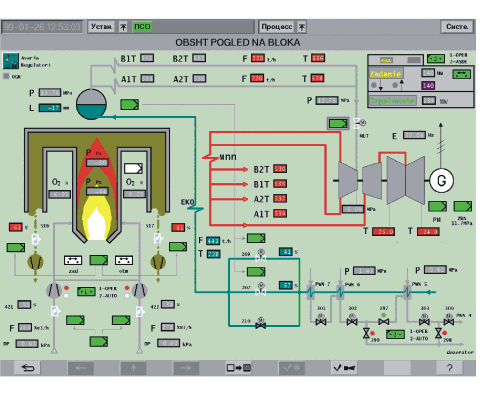
The operation switchings of the regulators are done from the operator station by means of a mouse from a relevant mnemonic from the screen. The mnemonic "Main view" is shown on fig.2. The options proposed from this mnemonic are selection of the regime of work of the regulators for the common air, thinning out in the furnace, drum level, as well as the transition from local control of РМ to an ASDC of the latter.
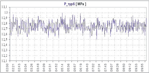
Without regard of the fact that on this stage the turbine was working with the original regulation valves and the hydro-mechanical system for control, which was degraded and with low Независимо от това, че на този етап турбината работеше със оригиналните регулиращи response time, the results, obtained from the secondary regulation of the load were the best among all the other thermal units in Bulgaria, working on a dispatch setpoint. A prerequisite for that was the very good maintenance of the nominal pressure before the turbine from the "Heat Load" Closed Control Loop system.
Figure 2. "Main view of the unit" mnemonic
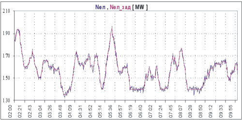
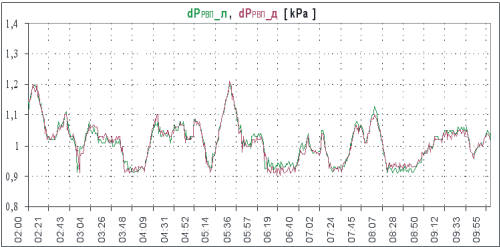
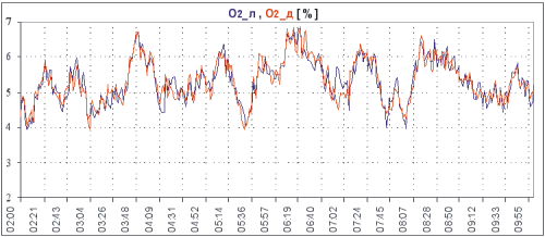
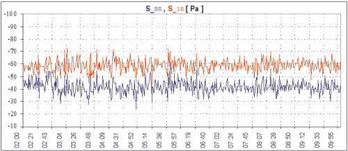
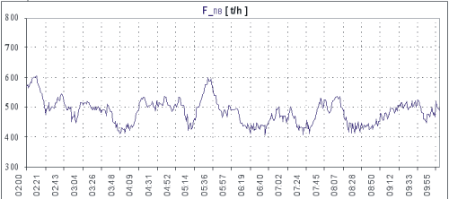
The following figures present the work of some of the main regulators during an ASDC regime
Figure 3. Setpoint and fulfillment of the electrical power
Figure 4. Pressure before the turbine in an ASDC regime
Figure 5. Pressure drop of the secondary air on the air-heaters
Figure 6. Oxygen consistence in the flue gases left and right
Figure 7. Thinning out in front and rear chambers
Figure 8. Feeding water flow
A basic conclusion, which is evident, is that the real generated power is following strictly and almost without delay the setpoint for power with a deviation of *3 МW. This is not enough though. It is important to see the behavior of the technological quantities, which assure the stable and economical work of the unit. The maximal deviations of these values from the setpoint in a current regime as follows:
Real Admissible *
Pressure before the turbine *0,2 МРа *0,26 МРа
О2 consistence *0,25% О2 *0,5% О2
Thinning out in the furnace *10 Ра *20 Ра
Drum level *5 мм *20 мм
Overheated steam temperature *4*С *6*С
* "Teploenergetika" 1985, book 10
The same deviations in a dynamical regime are at the rate of:
Real Admissible *
Pressure before the turbine *0,15 МРа *0,32 МРа
О2 consistence *0,5% О2 *1% О2
Thinning out in the furnace *25 Ра *30 Ра
Drum level *10 мм *50 мм
Overheated steam temperature +5,-10*С *8*С
Secondary steam temperature +5,-15*С *10*С
It is clear form the latter diagrams that the air and feeding water flows are smoothly changing, in accordance to the change of the setpoint for power and the regime card of the boiler. The regulation parameters are steadily stabilized in the admissible technological limits. The good results can be explained with the smooth (3 МW/min), and not a peak change of the setpoint. The considerable dynamic deviations of the thinning out in the furnace is a result of the great distortion when switching the air fans from first to second speed and backwards, but this tough regime is managed without any side interference too.
During the summer of year 2000, the accumulated experience and the perfect results for Unit 6 that were obtained became a basis for the erection of two new systems for control, at first for Unit 5 and afterwards for Unit 4, that covered almost all of the boiler and turbine control. The new systems included two base stations each, for the boiler and the turbine respectively, two operator stations and a new engineer station. Except that the regulating valves of the turbine of Units №4,5 and 6 were changed and a system for turbine control SIMADYN D from SIEMENS was delivered. In the boiler part and the systems for regeneration of the turbine were included the following control loops and FGC (Functional Group Control):
Automatic control systems
- CCLS "Electrical power"
- CCLS "Heat load of the boiler"
- CCLS "Common air with a correction of the oxygen in flue gases"
- CCLS "Thinning out in the furnace chamber"
- CCLS "Drum level"
- CCLS "Primary air pressure"
- CCLS "Primary steam temperatures" - I, II and III injections
- CCLS "Secondary steam temperatures" - Secondary Steam Heater and emergency injections
- CCLS "Thinning out before fan mill A and B"
- CCLS "Feeding water for injection pressure"
- CCLS "Level in low pressure heaters"
- CCLS "Level in high pressure heaters"
- CCLS "Condenser level"
- CCLS "Deaerator level"
- CCLS "Deaerator pressure"
- CCLS "Pressure in steam collector for thickening"
- CCLS "ПН100 level"
- CCLS "Pressure after РОУ2 and РОУ3"
- CCLS "Pressure before БРОУ"
Functional group controls
- FGC of dust feeders with slide valves primary and secondary air;
- FGC of air fans;
- FGC of high pressure heaters.
Actually, the systems of all the three units are linked through the inner network of the plant, which is a factor for building the so-called "multi-unit structure", allowing the supervision of process data by clients of the network and through Internet.
On the other hand, the integration of the system for control of the turbine into the entire system for control assures the complete realization of any advanced control systems, because the exchange of any data between boiler and turbine is unlimited.
On power unit №5 is realized a coordinated control of the electrical power and the heat load, by using the above mentioned principle, but assuring a much better regulation quality as well as full process information for the operation personnel. The implemented system is a factor for the further extension of the works for the erection of a fully automated man-machine interface without any control boards.
The "multi-unit structure" gives the possibility for the realization of calculation functions, connected with the load distribution between the working units, in dependence of their state, technological limitations and efficiencies.
Figure 9. System structure